
Based on build mechanisms and material systems, 3D printing technologies can be categorized into several process families. Different processes have their own trade-offs in terms of accuracy, strength, cost, and application scenarios. This section focuses on several widely adopted and representative technologies.
Material Extrusion
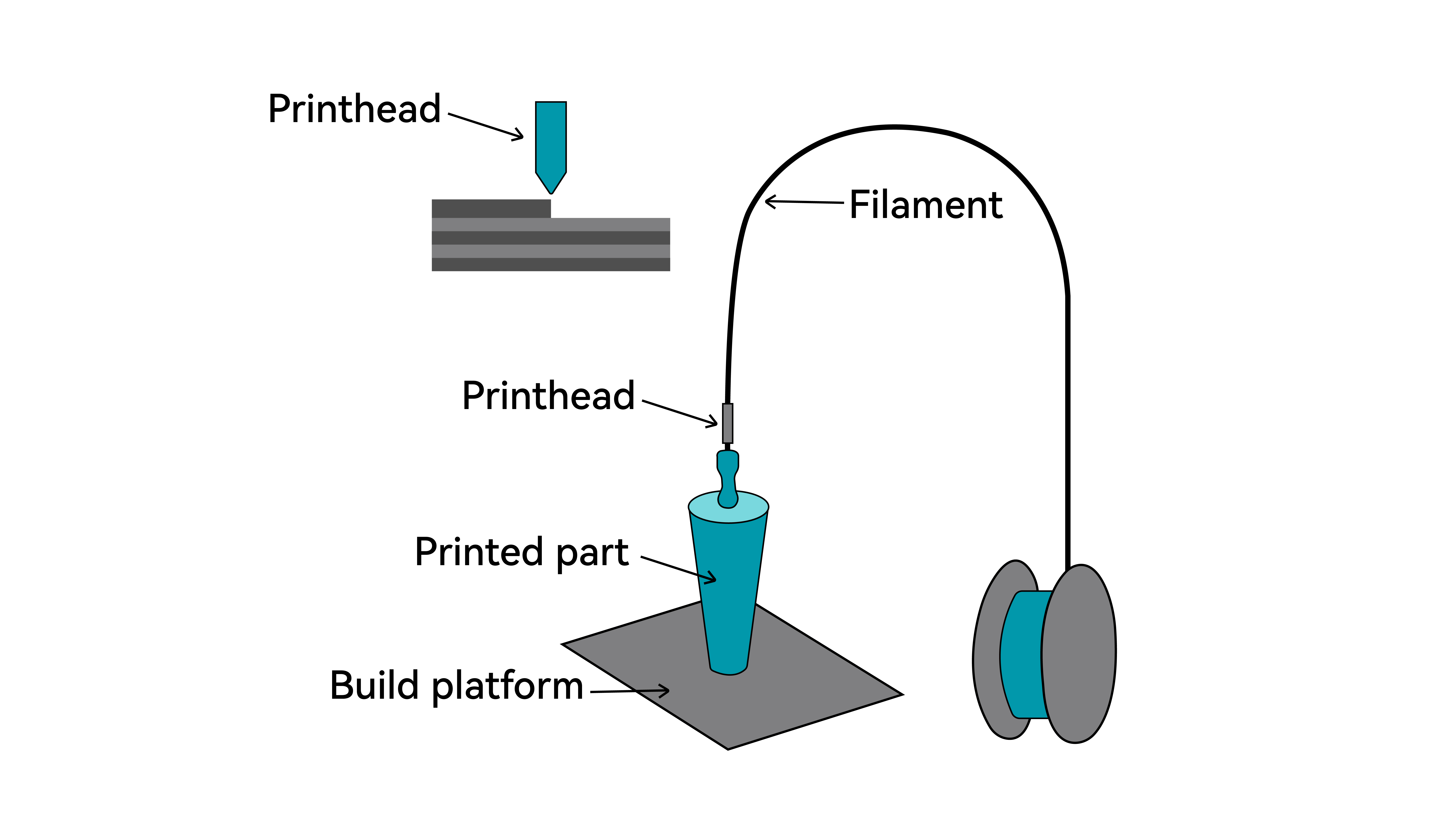
Material extrusion is an additive manufacturing process in which material is heated through a nozzle to a molten or semi-fluid state. A motion system follows a predefined path to control the extrusion of material, depositing it layer by layer and allowing it to solidify into a three-dimensional structure.
This process is centered on continuous material extrusion and is compatible with a wide range of materials, including thermoplastics, metal and ceramic slurries, and even concrete. Overall, this process features relatively simple equipment structure, low cost, and ease of implementation, making it one of the most widely adopted 3D printing technologies today.
Fused Deposition Modeling (FDM)
Fused Deposition Modeling (FDM, registered trademark of Stratasys) is a material extrusion-based 3D printing process, also referred to by the alternative names "FFF", "FFM", and "PJP". It is one of the most widely adopted 3D printing technologies in both consumer and professional environments.
The process uses thermoplastic filament as feedstock. During printing, the filament is fed into a heated hot end where it is melted and extruded through a nozzle. The print head moves along programmed toolpaths in the X–Y plane, depositing molten material onto the build surface or previously printed layers. After deposition, the material cools and solidifies, forming a bond with the underlying layer.
Once a layer is completed, the system shifts along the Z-axis by a predefined layer height, and the next layer is deposited. This layer-by-layer process continues until the final three-dimensional object is formed.
Key Characteristics of FDM
Advantages
1. Accessible and Cost-Effective
FDM is one of the most widely adopted 3D printing technologies due to its straightforward mechanical design and relatively low system cost. Both printers and filament materials are generally affordable and easy to maintain.
2. Wide Material Availability
A broad range of thermoplastic filaments is available, including PLA, ABS, PETG, nylon, and flexible materials. This variety allows FDM to cover applications from visual prototypes to functional parts.
3. Clean and Practical Operation
Compared to resin or powder-based technologies, FDM systems are easier to operate and typically require less post-processing. When properly ventilated, they are suitable for home, educational, and office environments.
4. Efficient for Prototyping and Iteration
Because no molds or tooling are required, design changes can be implemented quickly, making FDM well suited for rapid prototyping and small-batch production.
Limitations
1. Visible Layer Lines
The layer-by-layer extrusion process naturally produces visible layer lines. Surface finishing may be required for applications where appearance is critical.
2. Limited Fine Detail
Print resolution is influenced by nozzle diameter and layer height. Very small features and sharp details may be more difficult to reproduce compared to photopolymer-based technologies.
3. Mechanical Anisotropy
Since parts are built in layers, bonding between layers is typically weaker than within each layer. Print orientation should therefore be considered when designing load-bearing components.
4. Print Speed Constraints
Large solid models or high infill settings can result in long build times due to the sequential deposition process.
FDM Process Workflow
1. Material Preparation
FDM uses thermoplastic filament as its raw material, typically supplied on spools with diameters of 1.75 mm or 2.85 mm. Common materials include PLA, PETG, and ABS. Filament must be kept dry before printing. Moisture can cause issues such as bubbling, stringing, and poor layer adhesion. It is recommended to store filament in a dry box or to dry it prior to use.
2. Heating and Melting
The filament is fed into the print head (hotend assembly) by the feeding mechanism. It enters the heating zone near the nozzle, where the temperature is raised above the material’s melting point (typically 180–400°C, depending on the material), transforming the solid filament into a viscous, flowable state.
3. Extrusion and Deposition
The molten material is continuously extruded through a small nozzle opening (typically 0.2–0.6 mm in diameter). It is deposited onto the build plate or previously printed layers, forming a three-dimensional object through layer-by-layer stacking and cooling.
4. Interlayer Bonding
After deposition, the extruded material rapidly cools and partially solidifies. The heat from newly extruded material slightly remelts the surface of the previous layer, enabling thermal bonding between layers and forming a cohesive structure.
5. Post-Processing
After printing, parts usually require post-processing to meet final application requirements. Common methods include support removal, sanding, bonding, and annealing.
Fused Granular Fabrication (FGF)
FGF is an additive manufacturing process based on thermoplastic melt deposition. Unlike FDM, which uses filament, FGF directly utilizes thermoplastic pellets.
Pellets are fed into a hopper, melted in a heated chamber, and driven by a screw mechanism before being extruded through a nozzle.
FGF can use injection-grade pellets directly without converting them into filament, significantly reducing processing time and material cost. The use of pellets also enables higher extrusion flow rates, making FGF particularly suitable for large-scale plastic parts.
Key Features of FGF 3D Printing
Advantages
- Lower material cost: Direct use of injection-grade pellets eliminates filament production costs.
- Flexible material selection: Supports reinforced (glass fiber/carbon fiber), flame-retardant, anti-static, and even recycled materials.
- Large-format printing capability: Commonly used in industrial-scale 3D printers.
- High extrusion efficiency: Screw-based extrusion enables high flow rates, ideal for fast production of large parts.
Limitations
- Lower precision and surface quality: Larger nozzle diameters typically result in rougher surfaces.
- Material and process constraints: Requires good pellet flowability; fine or agglomerated particles may cause unstable feeding or clogging. Material switching can be difficult and wasteful.
- Higher equipment requirements: Machines are usually large, expensive, and require industrial power and compressed air. Maintenance is more complex due to components such as screws, nozzles, and cooling systems.
FGF Process Workflow
1. Material Preparation
Most pellets must be pre-dried in a drying oven to remove moisture. Ensure uniform particle size and absence of dust or clumping before loading into the hopper or conveying system.
2. Heating and Melting
Pellets are transported by a rotating screw into the barrel, which contains one or more heating zones. The material is gradually melted into a uniform blend, while the screw mixes it thoroughly to ensure consistency.
3. Extrusion and Deposition
Pellets enter the barrel through the hopper and are conveyed forward by the rotating screw. As they pass through segmented heating zones, they are melted, compressed, and homogenized, then continuously extruded through the nozzle under pressure.
4. Interlayer Bonding
When the newly extruded high-temperature material contacts the previously solidified layer, localized remelting occurs on contact. This enables thermal bonding between layers, forming a unified structure.
5. Post-Processing
Due to larger nozzle diameters and thicker layers, FGF parts often have rough surfaces and visible layer lines. Post-processing is typically required, including cleaning, sanding, heat treatment, and painting.
Vat Photopolymerization
Vat photopolymerization uses photosensitive resin as the raw material. Under computer control, a UV laser selectively cures the resin layer by layer to form a solid object.
This process enables the efficient and fully automated production of prototypes with high surface quality, high dimensional accuracy, and complex geometries.
Vat Photopolymerization Process Workflow
1. Model Preparation
Resin printing requires careful model orientation and support design. Proper angling reduces suction forces and minimizes surface marks, while supports must ensure stability during printing and allow clean removal afterward.
2. Slicing Setup
Using dedicated resin slicers such as ChiTuBox or Lychee, key parameters are configured, including exposure time, lift speed and distance, and anti-aliasing settings. The software outputs a printer-specific file containing layer images and motion data.
3. Machine Setup
Before starting a print, complete the following checks and preparation steps:
- Check resin level: Make sure there is enough resin in the tank to complete the print.
- Mix the resin: If the resin has been sitting for a long time, stir or shake it for 1–2 minutes to ensure it is evenly mixed.
- Inspect the release film: Check for scratches, dents, or damage. Replace if necessary.
- Install the resin tank and build platform: Ensure both are securely mounted. The build platform must be properly leveled.
- Load the print file: Import the sliced file into the printer.
4. Printing
The build platform moves into position—either lowering into the resin (bottom-up systems) or positioning near the resin surface (top-down systems).
A light source (laser, DLP projector, or LCD mask) selectively exposes the first layer pattern, curing the liquid resin into a solid layer. This layer adheres firmly to the build platform and forms the foundation of the print.
Layer-by-Layer Curing and Platform Movement:
(1) Bottom-Up Systems (Most Common)
- After a layer is cured, the build platform lifts slightly (Z-axis movement), separating the cured layer from the release film.
- The platform pauses briefly to allow resin to flow back into place.
- The platform lowers to the next layer position (one layer height above the previous layer).
- The light source cures the next layer, bonding it to the previous one.
(2) Top-Down Systems
- After a layer is cured, the build platform moves downward by one layer height.
- A blade or roller recoats a fresh, even layer of resin over the surface.
- The light source cures the new layer from above.
- This cycle repeats until the part is fully formed. Depending on the machine design, the part may be built in an upright or inverted orientation.
- Environmental control: Maintains a stable ambient temperature and keeps the printer enclosure closed during operation.
- Monitoring: The process should be thoroughly monitored, including resin level and machine status, for the entire duration of the print.
5. Post-Processing
After the final layer is cured, the build platform will either raise (bottom-up systems) or lower (top-down systems). Users should wear protective gloves and safety goggles before removing the part, which is still covered with uncured resin and attached to the support structures. Allow excess resin to drain off while the part is still on the build platform, then carefully remove it from the platform.
Next, place the part—together with its supports—into a cleaning solvent such as isopropyl alcohol (IPA) to remove residual resin. It is recommended to remove supports while the resin is still in a partially cured state, followed by a second cleaning if needed.
Finally, transfer the part to a UV curing unit for post-curing to achieve the intended mechanical properties. Additional finishing steps, such as sanding or painting, can be performed as required.
SLA 3D Printing
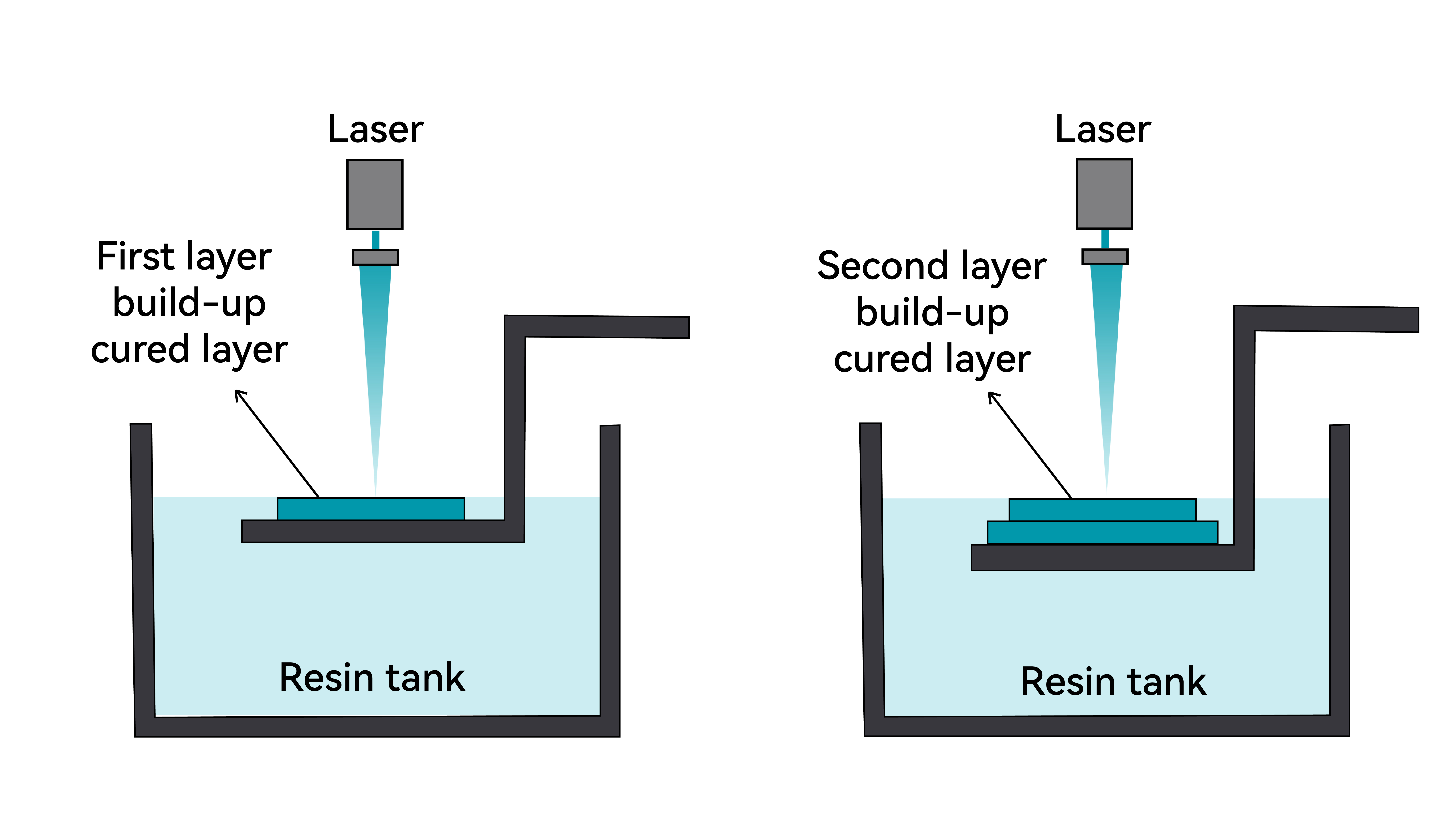
SLA (Stereolithography Apparatus) is a laser-based vat photopolymerization process. It uses a focused ultraviolet (UV) laser to scan and cure liquid photopolymer resin point by point.
Under computer control, the laser traces the cross-sectional geometry of each layer on the surface of the resin. The exposed areas rapidly solidify through photopolymerization. Once a layer is completed, the build platform moves by one layer height (up or down, depending on the machine design), allowing fresh resin to cover the previously cured layer. This process repeats layer by layer until the final 3D object is formed.
After printing, the part is removed, cleaned to eliminate uncured resin, and post-cured under UV light to achieve its final mechanical properties.
Key Characteristics of SLA
Advantages
1. Exceptional precision and fine detail, suitable for complex geometries
2. Excellent surface finish, with minimal visible layer lines
3. Wide material range, supporting various applications
Limitations
1. Slower print speed due to point-by-point laser scanning
2. Higher equipment cost
DLP 3D Printing
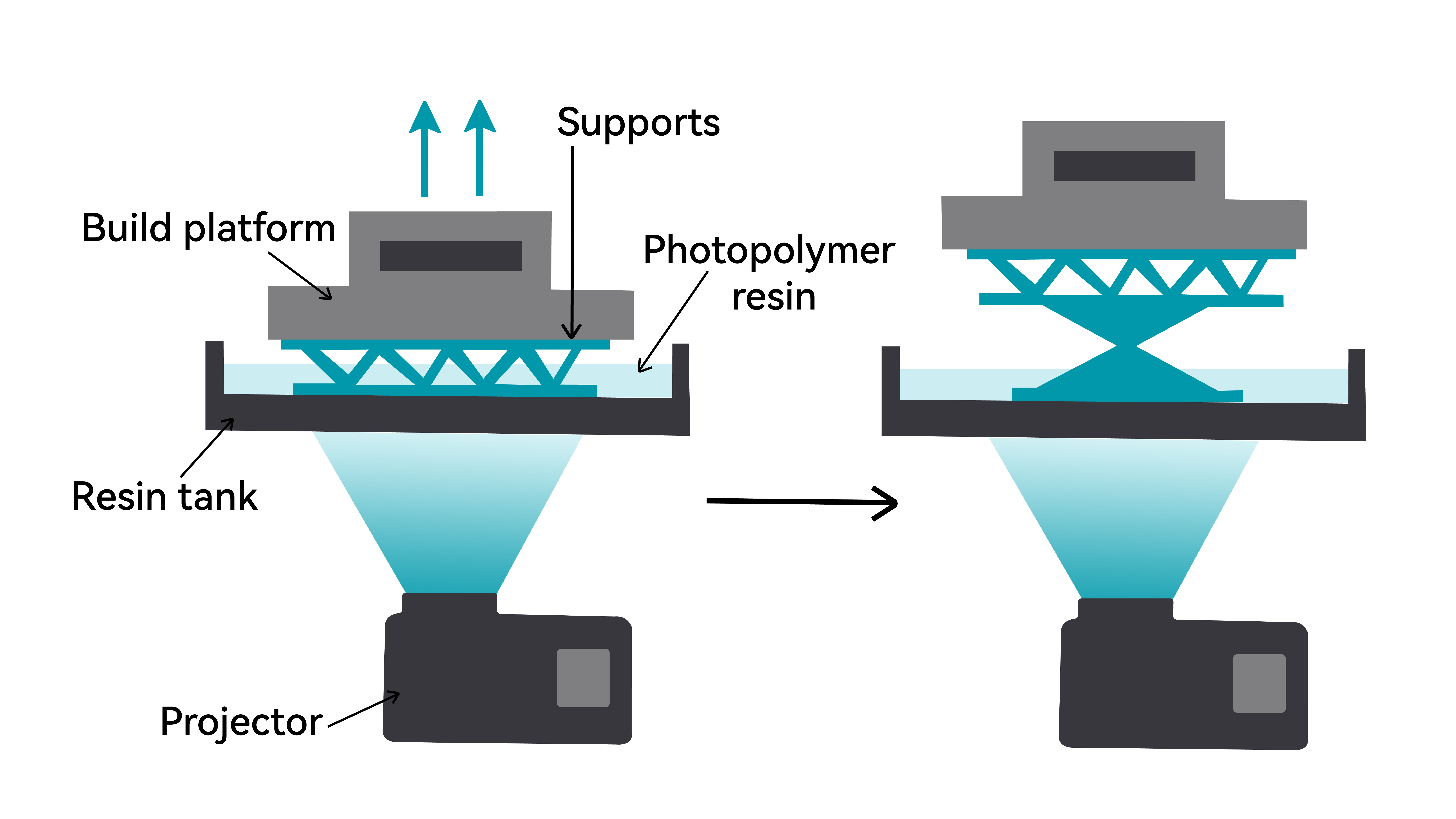
DLP (Digital Light Processing) is a vat photopolymerization process that cures an entire layer at once.
Unlike SLA, which scans point by point, DLP uses a digital projector to flash a complete cross-sectional image of each layer onto the resin surface. The illuminated areas cure simultaneously, while dark areas remain liquid.
Because each layer is exposed in a single step, print time per layer is constant and does not depend on the complexity of the geometry. As a result, DLP is typically faster than SLA, especially for parts with large or complex cross-sections.
The rest of the workflow—layering, platform movement, cleaning, and post-curing—is similar to SLA.
Key Characteristics of DLP
Advantages
1. High printing speed, as each layer is cured simultaneously. Consistent build time per layer, independent of XY complexity.
2. Good accuracy and detail reproduction
3. Durable light source (projector-based system)
Limitations:
Resolution depends on projection size: As the build area increases, pixel density decreases, which can reduce fine detail quality
LCD 3D Printing
What Is LCD 3D Printing?
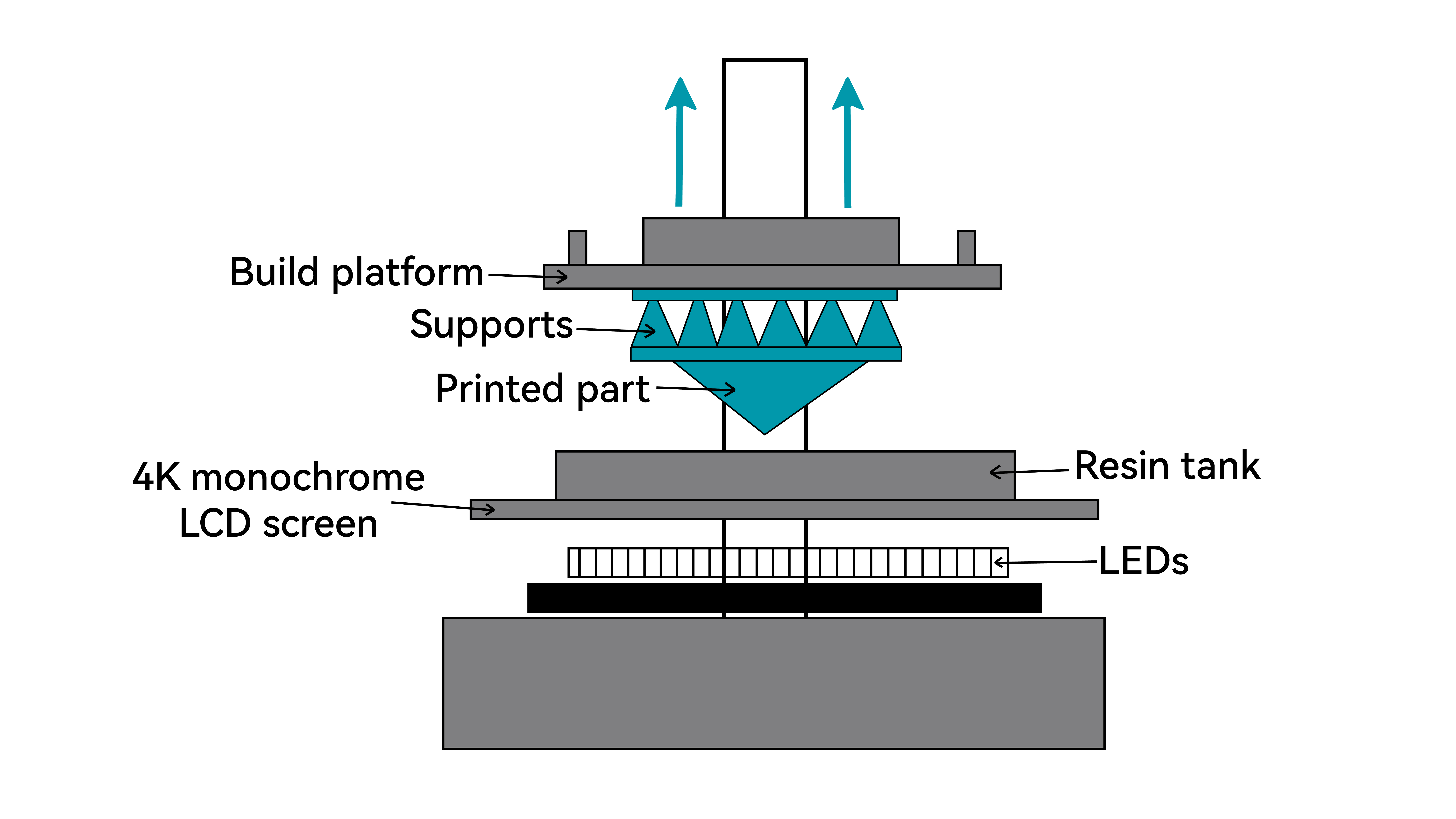
LCD 3D printing is a resin-based photopolymerization technology that uses a high-resolution liquid crystal display as a dynamic mask.
During printing, the LCD screen projects a sliced image of each layer of the 3D model. A UV LED array beneath the screen emits uniform ultraviolet light, which passes only through the transparent areas of the mask and cures the liquid photopolymer resin inside the vat in a single exposure. The exposed resin undergoes rapid polymerization and solidifies into a precise layer.
The build platform then lifts incrementally, repeating the process layer by layer, allowing the part to be formed directly from liquid resin with exceptional surface detail.
Key Characteristics of LCD Printing
Advantages
1. High cost-to-performance ratio
LCD technology delivers excellent resolution while keeping hardware costs relatively low, making professional-grade precision accessible to designers, educators, and hobbyists.
2. Fast layer curing
Each layer is exposed and cured simultaneously, meaning print time per layer remains constant regardless of model complexity.
3. Outstanding detail reproduction
Ideal for applications requiring fine features and smooth surfaces, such as jewelry patterns, dental models, precision components, and collectible figurines.
Limitations
1. Material handling requirements
Liquid resins can irritate skin and release fumes. Proper ventilation and protective equipment are essential.
2. Post-processing intensity
Printed parts must be washed, support structures removed, and UV post-cured. The process generates chemical waste and requires additional equipment.
3. Consumable components
LCD panels and release films are wear items that require periodic replacement and may affect long-term accuracy.
4. Mechanical brittleness
Standard resins are generally more brittle and less fatigue-resistant than engineering thermoplastics, and may yellow or degrade over time.